SlinkRocket
Protocol and IP cores
SlinkRocket is the protocol used to transmit data form the FED ATCA card to the DTH card. See below for the data format. The protocol is used over an optical physical link working at 15,66 Gb/s or 25,78125 Gb/s. The protocol uses up to 4 blocks of 4Kbytes to transmit fragments on the fibre. Each block includes a CRC to validate it at the reception (USB CRC16 code here or link(1) (2)). However this protocol is hidden from the user. The user interface of the SLINKRocket is conceptionally very similar to the previous generation of the SLINK protocol.
The SlinkRocket cores (sender and receiver) are available in GitLab as an IP for Xilinx FPGA (only for Kintex and Virtex Ultrscale+. Currently also a version for the Kintex Ultrascale series is available but it will no be supported in the long term). Be sure to use tagged versions and not the master branch. The Users manual for the IP cores can be downloaded from Gitlab.
There exist two example designs implementing one or 4 Slink Rocket links with VCU118 development board of Xilinx. How to compile this design is described in the SlinkRocket Users Manual mentioned above.
Firmware Dependencies
There are some dependencies between the versions of the IP cores and the DTH-Kit firmware. These are listed in the table below. Be sure that you satisfy these dependencies when you upgrade your firmware (i.e. there are situations in which you have to upgrade the Core firmware and the DTH-Kit firmware at the same time in case you want to send data from the core to the DTH Kit. )
| IP Core firmware | DTH-Kit daq firmware | Remark |
|---|---|---|
| up to v03.04 | up to dth_p1v2_daq_[15|25]g156gty_001_000_003 | |
| v03.05 | at least dth_p1v2_daq_[15|25]g156gty_001_002_000 | A change in the low level handling of link synchronisation creates this dependency. |
| v03.07 | at least dth_p1v2_daq_[15|25]g156gty_001_002_000 | A bug fix, which could cause the link to block in the receiver core. |
| v03.09 | at least dth_p1v2_daq_[15|25]g156gty_001_002_000 | A bug fix. (sender would block with small event sizes). |
| v03.12 | at least dth_p1v2_daq_[15|25]g156gty_002_002_001 | The receiver IP is now using UltraRAM. The trailer of the SlinkRocket format has been changed according to the EDMS document 2502737: The DAQ adds its own CRC to the trailer and the Sub-system CRC is never overwritten. |
Firefly
The media used is Firefly (SAMTEC). The Firefly used has 4 fibres as transmitter and 4 fibres as receiver working up to 28Gb/s per module. The same media is used when SlinkRocket works at 15.66 Gb/s, in this configuration, the internal CDR is switch OFF.
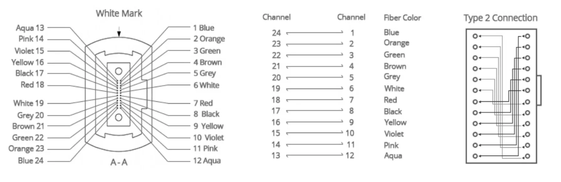
To concentrate connections at the front panel, we decided to merge 2 firefly’s per MPO connector. You can find the MPO connectivity in this file : OTP-215336-xx-ECUO.pdf
The front panel connection to the firefly is done via a MPO adapter (KeyUP/KeyDown). To connect your SlinkRocket to the DTH you have multiple choices.
- You have a MPO24 coming out of your card and the fibre positions are the same as our Firefly (see OTP-xxx.pdf file above)
- you can use such a cable https://www.fs.com/fr/products/30931.html type B (drawing coming soon)
- You have a MPO12 coming out of your card and the fibre position is compatible with our firefly
- FS.COM (or others) can provide custom MPO24 to 2x MPO12
- You do not comply with the 2 above solutions, in this case is better to use a breakout MPO24 to LC fibre cable
- you can use such a cable https://www.fs.com/fr/products/31191.html type B (in this case you have all the flexibility)
Don’t hesitate you to ask if you have a doubt on the connectivity. You can find also a fibre polarity explanation here
The first firmware version will use the connection RX0/TX0 for the first SlinkRocket receiver connection. A second version will come later with a second SlinkRocket receiver using RX1/TX1.
On the first firmware version (DAQ FPGA) a SlinkRocket transmitter is implemented for debuging. It uses the connection RX4/TX4 (the second Firefly connected to the MPO).
MPO loopback
For debugging, a loopback module is provided for test purpose. This module has these characteristics: 24 fibres OM4 loopback type 2 (clock on picture to see how loopback is connected)
IBERT for debugging
A design with IBERT on both Firefly (SlinkRocket connections : sender and receiver) can be found in gitlab: IBERT_DESIGN
A readme.txt file explains how to use the firmware and the software. Launch the software first before programmig the FPGA, and use the HELP option to know what to do .
The clock generator has to be reprogramme because IBERT doesn't use the same clock reference as the SlinkRocket design (this will be done with the software). This clock configuration will lost after a DTH power cycle .
If you want to come back to the standard DTH configuration, power cycle the DTH.
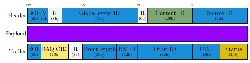
Event fragment
Event Fragments send by sub-detectors have to fulfill a format. The word size is 128 bits. The format is composed by a Header, a payload (which can be empty) and a Trailer. The Header and Trailer formats are defined in: https://edms.cern.ch/document/2502737/.